Technique
(shown for proximal humerus and distal tibia)
Click on image for enlarged view
1 Reduce the fracture
Reduce the fracture to restore anatomic
alignment and rotation. Confirm reduction
under image intensification.
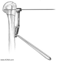
2 Insert the guide wire
Place the 90° Cannulated LC-Angle Blade
Plate Drill Guide [332.401] on the bone at
the intended position of the blade plate as
determined during preoperative planning.
Insert a 2.0 mm Threaded Guide Wire,
230 mm long [292.65], through the 2.0 mm
hole (middle hole) in the drill guide. This
orients the blade at 90° to the shaft of the
bone*. The tip of the guide wire should
engage the subchondral bone. Confirm
placement under image intensification.
Click on image for enlarged view
3 Drill the near cortex
Remove enough of the near cortex to allow
plate insertion by using a 4.5 mm Drill Bit
[310.44] through the holes adjacent to the
guide wire.
Remove additional cortical bone to allow
the plate to lie flush by using a 3.2 mm Drill
Bit [310.31] through the angled holes in the
drill guide.
Remove the drill guide.
*Note: If the plate is contoured, the orientation between the side plate
and blade my not remain 90°. It is recommended that the guide wire
be inserted without the drill guide (free hand) approximating the new
angle of the blade.
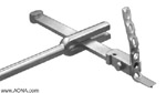
4 Measure for blade length
With the drill guide removed, use the measuring
device* [319.21] to determine the length of the
guide wire in the bone. Choose a blade length
at least 5 mm shorter than this measurement.
Using the 4.5 mm Cannulated Drill Bit [310.69]
over the guide wire, drill the near cortex.
* Note: A 230 mm long guide wire must be used for
accurate measurement with this measuring device.
Click on image for enlarged view
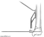
5 Insert the blade plate
For proximal humerus:
Insert the 90° Cannulated LC-Angle Blade Plate
over the guide wire. The blade will chisel through
a portion of the near cortex and displace a small
amount of cancellous bone*. Remove the guide
wire.
Place an oblique lag screw through the most
proximal plate hole to engage the far cortex.
Use 4.5 mm Cortex and 6.5 mm Cancellous
Bone Screws to fix the plate to the bone and
stabilize the fracture.
* Note: If the plate does not fit flush to the bone,
additional cortical hone below the guide wire
can he removed with a chisel.
Additional instruments for plate insertion
The Inserter/Extractor Handle [332.402] can be
used with the Small Slotted Hammer [332.403] to
aid insertion. Light mallet blows are recommended
in the proximal humerus to avoid over-insertion
or disruption of the fracture.
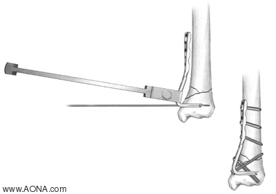
Click on image for enlarged view
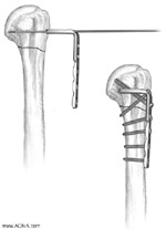
5 Insert the blade plate
For distal tibia:
Attach the Inserter/Extractor Handle to the
90° Cannulated LC-Angle Blade Plate. Insert
the plate over the guide wire. Use the Small
Slotted Hammer for rotational control while
using a mallet to advance the plate with light
blows to the insertion handle. The blade will
chisel through a portion of the near cortex
and displace a small amount of cancellous
bone. Remove the guide wire.
Place an oblique lag screw through the most
distal plate hole to engage the far cortex. Use
4.5 mm cortex and 6.5 mm cancellous bone
screws to fix the plate to the bone and stabilize
the fracture.
Implant Removal
Remove all screws from the plate. Attach the
Inserter/Extractor Handle as close to the blade as
possible on the 90° Cannulated LC-Angle Blade
Plate. Use light blows with the Small Slotted
Hammer on the Inserter/Extractor Handle to
remove the plate.